For my Manufacturing Processes course, I was given the task of modelling a Samsung Ultra S21 and creating an engineering drawing for it on SolidWorks. Most people would probably not have the latest Samsung phone model on hand, and for me personally, I am an iPhone user and I have never experienced having a Samsung phone before.
So, I did the best I could and searched for the specs of the Samsung Ultra S21 on the Samsung website.
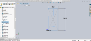
The general dimensions of the phone were: 75.6 mm width, 165.1 mm length, and 8.9mm thickness.
I was also able to find a 3D rendering of the Samsung S21 Ultra done by DatSketch on a website called Sketch Fab.
The rendering was super helpful because I was able to fully rotate the model and closely look at the shapes of the phone. And I was able to better approximate the placement of the cameras and other components such as power and volume buttons and approximate the size of the fillets on the edges and corners of the phone.
After taking the general dimensions from the Samsung website, I started up SolidWorks and got to work:
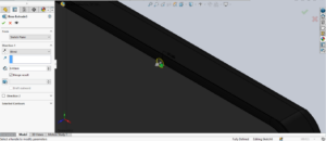
I first created a sketch of the phone on the Right Plane and I extruded it to 8.4 mm (because the screen would be 0.5 mm):
Using the same measurements from the initial sketch, I also extruded a screen, which was 0.5 mm thick:
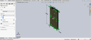
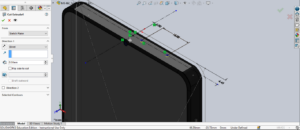
I then created a face fillet for the phone surface since it is not completely flat:
Next, I filleted the two edges of the phone so that I can get a smooth surface all around the phone:

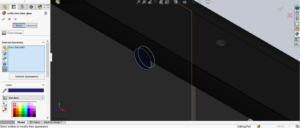
After modelling the general shape of the Samsung S21 Ultra, I started to look at the 3D rendering of the phone model to approximate the size and location of the charging port. I decided to sketch a rectangle with 4 fillets on each corner on the surface of phone:
After sketching the charging port, I used the Extruded Cut feature on SolidWorks to cut the slot to a 7 mm depth (approximated value):

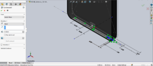
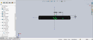
For the components related to the phone’s audio and microphone functions, I also created a sketch on the surface of the bottom of the phone. And I used the 3D rendering from Sketch Fab to help me approximate the size of the slots and circular patterns of the holes and distance between each component:
With my sketch drawn, I used the Extruded Cut feature to cut the holes to a 0.5 mm depth (approximated value):
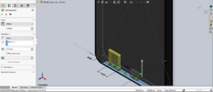
I also saw that the phone needed a place for the SD card, so I decided to sketch another slot (to the left of the charging port) on the surface of the phone:
I then used the Extruded Cut feature to cut the slot to a 12.35 mm depth (approximated value):
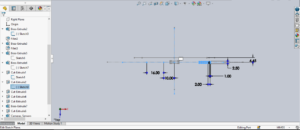
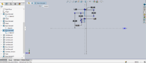
When looking at the 3D rendering, I was also able to find some holes that were used to either help people disassemble/re-assemble the phone, or to provide audio. Here, I sketched two circles and dimensioned them so that they were a certain size and were placed at a certain distance away from my centerline:
After Sketching these two top holes, I used the Extruded Cut feature to cut holes to a 0.5 mm depth (approximated value).
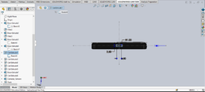
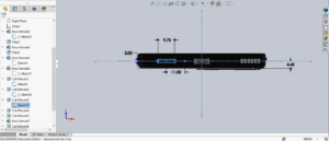
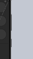
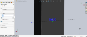
After making sure the details of the top and bottom of the phone were done, I looked to the right side of the phone, where the power button and volume buttons were. I approximated the sizing and placement of these buttons and sketched them onto the surface of the phone. In this sketch, I used centerlines to help me add relations between each button and align them properly:
Here, you can see the two types of buttons on the side of the phone:
Of course, I also had to include the Samsung Logo on the back of the phone. To do so, I sketched on the surface of the phone and used the text option to spell out the word “SAMSUNG” and I used Smart Dimensions to align it with the phone:
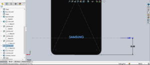
Once the sketch of “SAMSUNG” was created, I used the Extruded Cut feature to engrave the phone brand onto the back of the phone surface, and cut it to a depth of 0.05 mm (approximated):
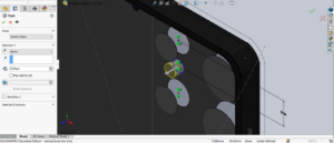
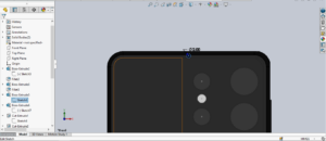
After I completed this logo for the phone, I consulted the Sketch fab 3D rendering to look at the frame that the cameras, sensors, and LED light were fit into. I approximated all of its dimensions and its placement and I sketched it onto the (back) surface of the phone:

I then approximated that the thickness of the frame would be 0.5 mm and I used Extruded Base/Boss to create it:

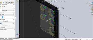
Next, I started working on the sketch for the cameras and sensors, and I approximated the dimensions and placements of all of these components. I used a linear pattern to achieve equally distanced circles for the phone cameras and used a reference line to position the sensors and LED light nicely:

I then used the Extruded Cut feature and cut the shape of these components to a 4.5 mm depth into the phone (approximated), and I also used the same sketch to make an Extruded Boss/Base with the same depth, so that I can later change the material of this extrusion:
After making the cuts for the cameras and sensors, I also cut a hole for the LED light to a 3 mm depth (approximated) and I followed the same step as I did for the (cameras and sensors) so that I can later change the material of the LED light’s extrusion:
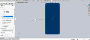
With the back of the phone’s components complete, I then worked on the last component, which was the front camera. I sketched a circle on the surface of the phone screen and I dimensioned it so that it was centered and an appropriate size:
After sketching the front camera, I used an Extruded Cut to cut the circular hole to a 0.4 mm depth and also sketched a separate circle of the same dimensions to fill it back in with an Extruded Boss/ Base (approximated) so that I can later changed the material of the camera lens:
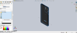
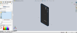
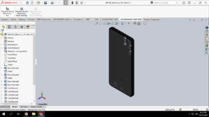
For a final touch, I changed the materials and appearances of the phone accordingly. For the Samsung S21 Ultra’s body. I changed it to a Black Medium Gloss Plastic:
And for the phone screen, I changed it to a Reflective Clear Glass:
Next, I changed the appearances of the front camera, back cameras, and sensors to a Blue Reflective Glass:

And lastly, I changed the appearance of the LED light to a White LED:

With my Samsung S21 Ultra complete, I saved the Part and imported the file into a SolidWorks Drawing so that I can show the phone in its standard views:
For my Drawing, I made sure to include all necessary dimensions and also ensured that everything is clearly visible and organized:
ME 462_Salina Liu HW#1 Final Drawing

This entry is licensed under a Creative Commons Attribution-NonCommercial-NoDerivatives 4.0 International license.